
Additionally, I thought it would be convenient to have a pack that allowed its cells to be changed out so that I could carry only as many cells as I expected to need. It turns out that there are not many commercial products that let you do that, so I decided to make one as a PCB design exercise.
Version 1
I threw together a quick design based on the TI BQ24165 battery charge management IC and the TI TPS61026DRCT 5V boost converter.
Note: There are some errors in this schematic.
I then did the layout of the board:

And sent it out to my preferred Chinese board house (JLCPCB at the moment).

I accidentally made the wire-mounting holes a bit smaller than I intended, but other than that, the boards looked good. I assembled one to test:

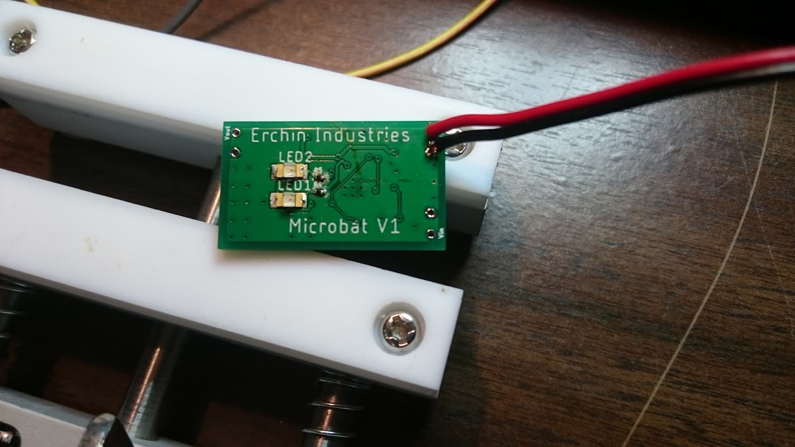
I connected this power input side of this board to a power supply set at 5V. This should have caused LED2, which is connected to the "Power Good" pin on the BQ24165, to light up, but it did not. I re-checked all of the solder connections and everything looked fine, so I went back to check the schematic against the datasheet for the BQ24165.

Whoops... Some little blue wires fix the problem and the board mostly behaves as I expect it to.

It does require a slightly higher voltage than I expect to decide that the charging supply is "good", which I found concerning, but it properly supplies 5V when a 3.7V supply is connected across the battery terminals. At this point the summer was coming to an end, so I had to go back to school. I fixed the schematic in Eagle in preparation for the next revision and paused development. This was the end of Version 1.
Version 2
I picked up the project again in October and decided that the rectangular board was annoying to incorporate into a compact package. This led me to re-design the PCB with a circular form factor.
Other than correcting the previously discovered errors, the design did not change and the PCB layout was fairly quick.

I chose to make the positive battery terminal a large circular via in the middle of the board with the thought that the positive contact could just be a screw that went through the hole. The battery ground contact was a big rectangular pad to allow a variety of mounting options. Additionally, I put all components on the top of the board to allow it to be mounted flat in some kind of case.
I ordered this board and it showed up eventually after being stuck in customs for an unusually long time.
The astute reader will note that I never actually figured out why the supply pin only "kind of" worked. After assembling one of these boards, I realized that I forgot to connect the PGND pins to ground, which left the voltage divider used to sense the supply voltage poorly referenced because it was connected to the PGND pins. I'm not entirely sure why I connected the schematic that way in the first place, but it was an easy fix and now everything actually works.
That's it for the board, so let's take a look at the case. My first idea was to mount the board in the cap of a twist-lock tube and use EMF gasket material to electrically connect the cap to a ring of copper tape on the main body of the tube. This had the benefit that I could potentially make it waterproof with some O-rings and clever glue application.


I 3D printed this case design when I was home for Thanksgiving.

My EMF gasket idea did not work at all. After I twisted the cap on, it was impossible to remove because the EMF gasket shredded itself by rubbing against the plastic of the tube.
Since the twist-on cap obviously wasn't going to work, I switched to a much simpler design where the board was held in a groove in a U-shaped piece:

This design uses the big via on the board that I originally panned to put a screw through as the positive contact for the battery. This isn't really ideal, but it works well enough for my purposes.

I added a cover so that the big inductor wouldn't decide to run away when inadvertently subjected to shear loads. I also added a little notch that is a tight fit on a USB cable as strain relief and some notches to make the battery easier to remove.

I'm mostly happy with the result. I'll probably build a few more for friends and maybe sell them in small quantities if I get enough interest.