Pages

Saturday, March 30, 2019

Impulse Response

I saw the Robojackets 20th Anniversary Competition listed on one of the various competition listing sites and impulsively signed up for it. So began my latest beetleweight combat robot, Impulse Response. My initial plan for this competition was to resurrect Event Horizon with a new design that more heavily leveraged 3D printing, since I acquired a used Prusa i3 MK3 3D printer over winter break. After messing around with that design for a while and even buying some parts for it, I decided that I wanted something simpler and easier to maintain. This led to the conclusion that I should make a 3D printed undercutter.

Design

The vast majority of the design process for Impulse Response took place over the course of two days in late January. The design goals were simple:
  • Minimize the number of machined parts
  • Maximize reliability/ maintainability

Machined Parts:

The robot has only three machined parts; the weapon blade, one of the inserts for locating the weapon shaft, and a spacer that goes inside of the weapon pulley.

Reliability/ Maintainability

The weapon shaft is supported by two large bushings. This distributes the load from the weapon across a larger area of the frame. The bottom bushing is aluminum because it sees most of the load. The top is 3D printed. The weapon shaft includes a spacer that contacts the inner races of both weapon bearings and allows me to tighten down the shaft without side-loading the bearings.

The weapon motor drives the weapon with a belt, isolating it from shock loads.

The drive base uses brushed motors because they are easy to work with and are unlikely to have motor controller issues.

Foam wheels isolate the drive motor gearboxes from any hits the wheels might take.

The extensive use of 3D printing made the manufacturing of spare parts comparatively simple.

The frame is significantly over-built, allowing it to take direct damage without significant structural implications.

Impulse Response after two design days

I tweaked some minor details after this, but on the whole, things remained the same.

Manufacturing

 Manufacturing Impulse Response was exceptionally easy because almost everything was 3D printed.
I first printed a PLA mockup of the body to make sure everything fit.

PLA test print of main body
 Next I printed the body and some other parts in NylonG and waterjet cut the blade at the Invention Studio. Printing NylonG is interesting. I needed to add glue stick to the PEI printbed to get it to stick and I put the filament inside of a dehydrator beforehand to drive out all of the moisture. I observed some shrinkage in the Z direction with the NylonG, but it was not enough to cause an issue.
NylonG print of main body with quick fit of components
The electrical system was slightly unusual. I prefer driving with a pistol-grip transmitter, but the cheap Hobbyking transmitter does not mix channels for tank drive. To achieve this, I added an Arduino, which did the mixing and also controlled the weapon based on the channel three button on the transmitter. It took killing an Arduino for me to realize that the voltage regulators were not what I thought they were.
Code may be found here: https://github.com/echin98/robotEngineArduino

Rough electrical system fit
 After everything was together, I weighed the bot. It was substantially under weight. In hindsight, I should have waited to machine the weapon until after everything else was done and then adjusted the size to fill up remaining weight.
The robot is very under weight

 Testing

I took advantage of being home for Spring break to test the robot. The weapon immediately proved its power. Its first victim was the old frame from Event Horizon v1.
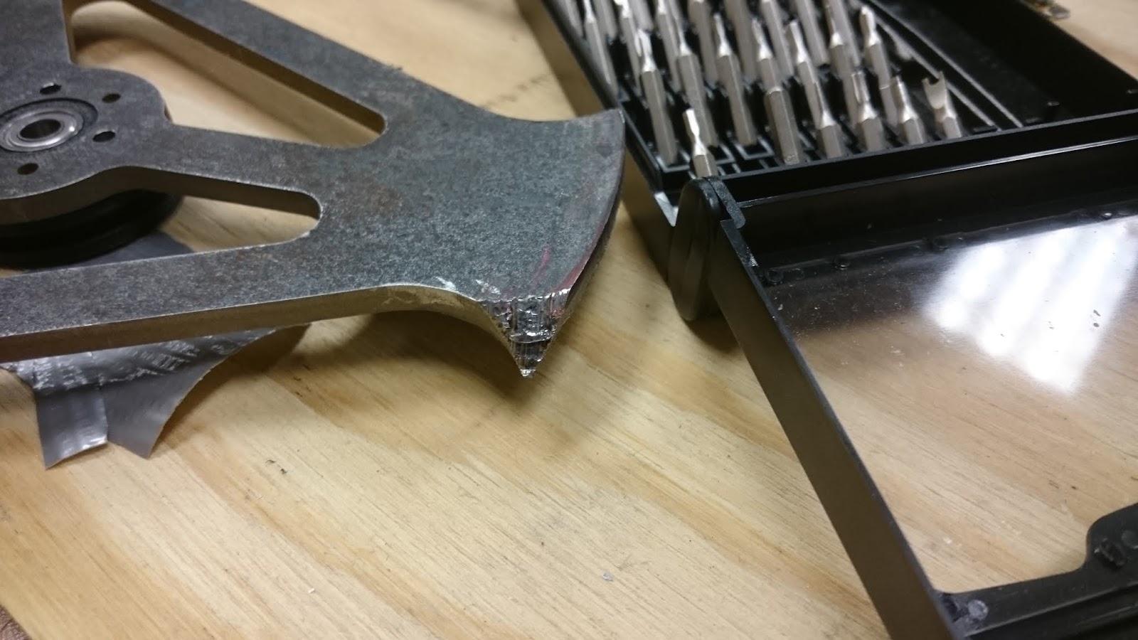
The corner of my test piece (the frame of EH v1) is machined off by the blade
In the course of testing, my weapon motor became hot enough to melt its PLA mounting block. I am still not entirely sure why it got so hot, though I suspect I just need to add some vent holes somewhere.

Whoops...

The weapon motor became excessively hot and melted its mounting block.
I replaced the PLA block with an aluminum plate. I also replaced the bottom retaining block for the weapon shaft with aluminum after cracking the original plastic piece.

Deeming it difficult to do more extensive testing, I decided Impulse Response was ready to go.
Impulse Response in its completed form


 Competition

Match 1: Loss vs Hypnotic

Hypnotic is a well-built drum spinner by a group of high-schoolers from Alabama. This was the first match ever for both robots, and I was eager to see how Impulse Response would fair. The match got off to a good start and I managed to bend Hypnotic's front floor skids. Shortly thereafter, my weapon embedded itself into the wood bumper in the arena. I was unable to get it unstuck and lost by KO.

Match 2: Win vs Large Hard

Large Hard is a drum spinner from the Rose Hulman robotics team. I was not entirely sure what to expect in this match as Big Hard had been partially disassembled by Hypnotic in its previous match. Unfortunately, my weapon failed to start up at the start of the match and it pretty much devolved into a pushing match. Big Hard lost its drive base partway through the fight and I managed to herd it into a corner where it couldn't use its weapon to get out.
By sheer luck, I won by knockout.
Watch RoboJackets 20th Anniversary - 3lb Combat Bots from RoboJackets on www.twitch.tv
I diagnosed the weapon problem to be a bad motor, though I was not entirely certain. I replaced the motor and added a ramp up to the firmware, which seemed to fix the issue. I also decided that I had limited the acceleration of the drive too severely and I increased that accordingly.

Match 3: Win vs Entropi

This was a quarter finals match.
Entropi is a beater bar style drum spinner from Robojackets. I was quite concerned about this fight because Entropi's beater bar was large and therefore high energy. I also was not 100% confident in my new weapon motor.
The fight started with us trading hits back and forth. I eventually landed a lucky hit on the inside of his weapon frame, causing his beater bar to eject.
Watch RoboJackets 20th Anniversary - 3lb Combat Bots from RoboJackets on www.twitch.tv
I took minimal damage.

Match 4: Loss vs Dynastinai

This was a semi-finals match.
Dynastinai is an undercutter with an extremely large direct drive motor. It was built by another Georgia Tech student and was formerly associated with Robojackets. I planned to try to take out his wheels and possibly damage his weapon motor since I had a reach advantage.
On the second hit Dynastinai flipped Impulse Response over. This proved catastrophic. The motor I used to replace the original weapon motor had a long shaft, which stuck out the top of the robot. This shaft contacted the ground before the intended contact point when the robot was flipped over and because the shaft was behind the center of mass, this left me unable to drive. Dynastinai cut into my top panel and stripped the battery wires, shorting them together. I lost by knockout and the battery went immediately into the sand bucket.
Watch RoboJackets 20th Anniversary - 3lb Combat Bots from RoboJackets on www.twitch.tv

Dynastinai's weapon is made from AR500 steel and this was what it did to my blade, which is made from AR400.

Match 5: Win vs Hypnotic 

This was the third place match.
Hypnotic and Impulse Response both sustained fairly heavy damage in our semifinals matches and we initially agreed to just run without weapons since those weren't working. We both managed to get our weapons working in time, though, so we used them.
I started picking away at Hypnotic's tires and eventually took off enough that it could no longer drive. Watch RoboJackets 20th Anniversary - 3lb Combat Bots from RoboJackets on www.twitch.tv
Impulse Response took third place behind Dynastinai and Mad. 

Post-Mortem

Overall, I am very pleased with the results of this competition.

Positives

  • The frame proved to be quite effective even after it had taken damage
  • All maintenance tasks were quick and easy to do
  • The robot could deal out big hits
  • The weapon system could take big hits without taking significant damage
  • The drive base was reliable

Negatives


  • Weapon electrical/motor system failed during the second match without obvious cause.
  • Weapon motor durability is not up to par; I had to replace the weapon motor twice
  • Weapon spin up time was too slow
  • PETG is not an appropriate combat robot material. I broke all of it.
The positives here are significant and the negatives are (I think) easier fixes. I will likely upgrade the weapon motor and ESC and also change the PETG parts to some other material before the next competition, whenever that might be. I may also upgrade the AR400 blade to AR500.  I feel no need to do a major redesign at this point.

Thursday, January 10, 2019

Microbat V2 - the Ultralight Backpacking Battery Pack

In the last two years or so, all of my backpacking electronics have become USB-charged. With this in mind, I wanted an extremely lightweight USB battery pack to replace this monstrosity:


Additionally, I thought it would be convenient to have a pack that allowed its cells to be changed out so that I could carry only as many cells as I expected to need. It turns out that there are not many commercial products that let you do that, so I decided to make one as a PCB design exercise.

Version 1

I threw together a quick design based on the TI BQ24165 battery charge management IC and the TI TPS61026DRCT 5V boost converter.


Note: There are some errors in this schematic.


I then did the layout of the board:

And sent it out to my preferred Chinese board house (JLCPCB at the moment).

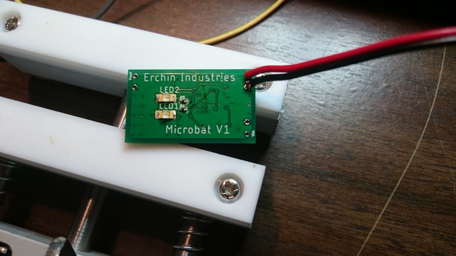
I accidentally made the wire-mounting holes a bit smaller than I intended, but other than that, the boards looked good. I assembled one to test:


I connected this power input side of this board to a power supply set at 5V. This should have caused LED2, which is connected to the "Power Good" pin on the BQ24165, to light up, but it did not. I re-checked all of the solder connections and everything looked fine, so I went back to check the schematic against the datasheet for the BQ24165.

Whoops... Some little blue wires fix the problem and the board mostly behaves as I expect it to.

It does require a slightly higher voltage than I expect to decide that the charging supply is "good", which I found concerning, but it properly supplies 5V when a 3.7V supply is connected across the battery terminals. At this point the summer was coming to an end, so I had to go back to school. I fixed the schematic in Eagle in preparation for the next revision and paused development. This was the end of Version 1.

Version 2

I picked up the project again in October and decided that the rectangular board was annoying to incorporate into a compact package. This led me to re-design the PCB with a circular form factor.

Other than correcting the previously discovered errors, the design did not change and the PCB layout was fairly quick.


I chose to make the positive battery terminal a large circular via in the middle of the board with the thought that the positive contact could just be a screw that went through the hole. The battery ground contact was a big rectangular pad to allow a variety of mounting options. Additionally, I put all components on the top of the board to allow it to be mounted flat in some kind of case.

I ordered this board and it showed up eventually after being stuck in customs for an unusually long time.

The astute reader will note that I never actually figured out why the supply pin only "kind of" worked. After assembling one of these boards, I realized that I forgot to connect the PGND pins to ground, which left the voltage divider used to sense the supply voltage poorly referenced because it was connected to the PGND pins. I'm not entirely sure why I connected the schematic that way in the first place, but it was an easy fix and now everything actually works.

That's it for the board, so let's take a look at the case. My first idea was to mount the board in the cap of a twist-lock tube and use EMF gasket material to electrically connect the cap to a ring of copper tape on the main body of the tube. This had the benefit that I could potentially make it waterproof with some O-rings and clever glue application.


I 3D printed this case design when I was home for Thanksgiving.


My EMF gasket idea did not work at all. After I twisted the cap on, it was impossible to remove because the EMF gasket shredded itself by rubbing against the plastic of the tube.

Since the twist-on cap obviously wasn't going to work, I switched to a much simpler design where the board was held in a groove in a U-shaped piece:

This design uses the big via on the board that I originally panned to put a screw through as the positive contact for the battery. This isn't really ideal, but it works well enough for my purposes.
I added a cover so that the big inductor wouldn't decide to run away when inadvertently subjected to shear loads. I also added a little notch that is a tight fit on a USB cable as strain relief and some notches to make the battery easier to remove.

I'm mostly happy with the result. I'll probably build a few more for friends and maybe sell them in small quantities if I get enough interest.


Saturday, February 10, 2018

Fairyweight Control System Part 1

I've started working on a fairyweight bot. This will largely be an electronics project because I'm building the control system from the ground up as an excuse to improve my C knowledge and learn PCB design.

The entire control board is based around a Silicon Labs Mighty Gecko wireless module, which is essentially a Arm Cortex processor with a wireless chip stuck on top of it on a PCB with a built in antenna  and matching network. I was originally going to use a discrete Gecko series chip and build my own antenna/ matching network, but I decided it would be better keep it simple and use the module to start with. The plan is to drive the motor controllers with the Mighty Gecko and use Bluetooth to send control signals from a computer.

I chose to use single chip motor drivers for both the drive motors, which are DC motors for now, and the weapon motor, which is brushless. The weapon controller is a fan controller, which can supply 1.5A. I think this should be sufficient for a fairly small and light spinning weapon.

I decided to use Eagle for my PCB design because it's free.

Here's the final schematic that I settled on:


And the final board layout:
 

This ended up being a four layer board with internal ground and power layers. I sent it off for manufacturing at Osh Park and got the three boards I ordered back in just under two weeks. I placed my Digi-Key order when I got a shipping notification from Osh Park and got it on the same day that the boards arrived. 

Upon opening the package, I realized that I left the vias exposed and didn't label the connector pinouts. Lessons learned.

PCB with quarter for size

I built out the board in the Invention Studio with a soldering Iron and hot air reflow gun. It was a fairly time consuming process as I had to reflow each of the parts individually, though I think it came out pretty well. I heated the wireless module from the bottom side of the board to avoid incidentally reflowing all of its components and damaging it. Hopefully, there aren't any solder bridges to exposed vias under there. I need to get PTFE jaws for my Stick Vise. The nylon jaws got a bit melted from the reflow gun.


I realized that I used the wrong size connector for the debug header. The 2x5 connector pattern is supposed to be the same size as the connector on the ribbon cable. I'll hack something together for now and use the proper connector on the next version.


Some other thoughts:
  • I should have included signal and power LEDs for debugging purposes
  • I can probably make the board smaller with the proper size connector
The next step is software and testing, which will likely be an interesting endeavor.

Saturday, June 10, 2017

Finishing Event Horizon V3.2 Part 2: Machining

Much progress was made today. I will need to make a trip to the local plastic supplier to get the stock for the wheels and new front blocks, place an Online Metals order for the armor plates, and place a McMaster order for new shoulder bolts and a few other things. In the meantime, however, I got to work machining the new drum internals and side plates. I also need to work on machining the blades, which I have been avoiding for several months, but I am going to continue putting that off.

Before I do a spin up test with the blades, I'll need to make a testing box. It could be extremely dangerous if one of the blades comes off with the drum at full speed. They are sharp enough to shave hairs off of my arm.

The first things on the table are all of the 3/8" UHMW parts. I have taken to doing my CNC work in large sheets. Here is a sheet containing all of the parts that need to be machined. I will need to make fixturing pieces to do the finish machining on the new front blocks, but that is a project for another day.
CNC Sheet of changed parts

If anyone is curious, I use the HSM plugin for Autodesk Inventor for writing G-Code. My CNC router is running Mach 3.

I tried a new endmill for these parts. It is an Amana Tool 1/8" plastic cutting bit, which I tacked onto a re-stocking order of 1/8" aluminum cutting bits made by the same company. The finish was slightly better than the old 1/8" straight flute mill that I have used in the past. I used twice my normal cutting depth and it worked well. In the future, I think I will use a slower feed because the finish is a bit rough.

After finishing the new UHMW pieces, I went back to the drum and machined a new idler axle. Originally, I was going to make a press fit for the axle, but I decided that there are several situations that may warrant removing the axle, so I enlarged the hole slightly so that it is just a tight slip fit.
Idler shaft and motor in drum
The bearing system on the idler side of the drum is just the aluminum shaft resting in a hole in the frame member. I used a reamer to bore out the hole, which left a good finish. I then added some spindle oil. This resulted in a surprisingly smooth bearing, though I am concerned about frame deformations causing it to lock up. I think I'll leave it for now, at least until I have the opportunity to do some testing.

Drum attached to the new frame

Friday, June 9, 2017

Finishing Event Horizon V3.2 Part 1: Design

I have finally un-killed myself from the FRC season.

My first priority on Event Horizon is to fix the misalignment issue I saw after spinning up the new drum for the first time. It seems that I will need to make a solid connection from the idler shaft to the motor shaft in order to make a continuous solid body.  My first idea was to make a 3/8" aluminum shaft that presses onto the motor shaft. I bought a reamer for this purpose and re-designed the drum internals slightly.

New idler shaft
Then, I looked over the last revision of the design, and found a bunch of things that I was not particularly happy with and re-designed them. I was going to need to re-make the side pieces to accommodate the new idler shaft design on the drum, so it seemed reasonable to make more changes. The first of these was the serpentine belt run. I mostly used the belt run to reduce space and weight while still maintaining high traction wheels. After thinking about my design more, I concluded that I did not actually care about traction. If I ever get into a pushing match, I am probably going to lose that match anyway. As such, I got rid of the BaneBots wheels and replaced them with pulleys, which do not use serpentine belt runs and make everything thinner.
New wheels and bottom view of armor modifications
I then decided that the way I had mounted the front braces might result in stress concentrations near the weapon bearing mounts. I switched the mounting to pins, which resulted in interference between the pins and mounting screws. Thus, I offset the side plates and rounded the front corners of the braces. This is actually beneficial for a few reasons: 1) It makes it less likely that an undercutter blade will catch the edge of the armor plate 2) It lets me switch from plastite screws, which tend to strip out, to bolts.
Pinned front joint

Inside of the finished front block design

Outside of the finished front block design
It looks like I pretty much redesigned everything... I guess I have some machining to do.

CAD Model

Sunday, December 18, 2016

Event Horizon Design Update

In the past few weeks, I have overhauled almost every aspect of Event Horizon with the goal of making it more robust (Silent Spring proof). Hopefully, this will give a good overview of what I changed.

Drum

The drum is where most of the issues from the original design originated. Here are the changes made:
  • Added pin between sleeve and motor mount piece: This should prevent these two pieces from rotating in unfortunate ways and shearing the wires.
  • Added internal steel nut strip: If the teeth get ripped out, it won't trash the drum (as much). The nut strip also acts as a keyway for the piece attached to the output of the motor.
  • Removed clamping piece for motor output and replaced with a plate bolted to the face of the motor: The primary motive for this was reducing weight, but it also leaves more space inside of the drum for other modifications.
  • Moved idler bearing from drum to frame: Making those press fit pieces was a pain.
  • Added retaining rings and washer to idler shaft: This constrains the bending of the frame by putting the drum in tension when the two main frame pieces are pushed apart. I believe this will help prevent Silent Spring-induced explosions.
  • Switched to a shielded bearing for the motor side: The open bearing got filled with dirt and other crap, which made it very stiff. It is best to avoid having the bearing filled with dirt.
  • Added a nub in the frame piece that matches the wire cutout in the motor mount sleeve: This constrains the rotation of the drum and prevents it from pulling its own wires out as in the Gemini match at FI.
  • Switched to a continuous steel blade for a tooth: It is inset into the drum and should be much tougher. I may not bother with this if I don't have enough time to do the machining.
Washer added to the idler shaft
Keyway nub to prevent rotation
The internals of the drum
Full render of everything

Drive Base

Most of the changes to the drive base were aimed at weight reduction. Changes made:
  • Switched to brushless motors: They are lighter and should be faster. I'm planning on using these: https://hobbyking.com/en_us/turnigy-park300-brushless-outrunner-1380kv.html
  • Back wheel is no longer direct drive: This improves the space situation and some reduction is probably necessary for the new motors.
  • Front and back wheels are now different sizes: Improves packaging.
  • Aluminum hex hubs are switched for nylon: Weight savings.
New wheel configuration


Frame/ Armor

I made a lot of changes to the frame aimed at improving strength.
  • Re-worked front plate mounting: Should be less prone to screws ripping out, etc.
  • Extended belly pan forward: This will brace the frame further toward the front, helping to prevent the main plates from buckling.
  • Switched from finger joints to pins to locate center plate: Fewer giant cutouts = less bad things.
  • Moved belly pan holes: I moved holes to places that do not have as many holes, rather than just ignoring their existence. This should reduce the likelihood of catastrophic failures of the frame members.
  • Reduced angle of side armor: I did not find myself needing it at all at FI and the weight savings are probably worthwhile.
  • Removed middle armor support: The fewer holes the better and, again, I didn't really need the side armor.
  • Switched to aluminum top plate: It should be stronger (and look better) and I think I have the weight.
The new system for the front corners
What the inside looks like now (I didn't bother modeling the motors)

Extended belly pan and holes strategically placed to avoid other holes

Other Thoughts:

Hopefully I will be able to manufacture this over winter break. While there are changes that I probably will not get around to, I suspect this version will be much more competitive than the last. Some experimental things, like the brushless motors may end up not working, in which case I will switch them out for more known quantities.

Sunday, October 9, 2016

Franklin Institute Competition Post Mortem

I have been looking to compete in a combat robotics competition for a while, and my schedule and robot state finally lined up for the Franklin Institute NERC event (FI) this year. I spent the week before the event on the CNC and lathe making spare parts in anticipation of some likely failure modes.

My father and I took a train from Boston to Philadelphia Friday night before FI, and arrived at 4:30 am Saturday morning in a fairly sleep deprived state.  After waiting around in the train station for a few hours, we walked to the venue (about a mile) and checked in.

Event Horizon went through safety inspection without issue and weighed in at 3 lb. 0 oz. Over the course of the next few hours, the pit area filled up completely. All in all, around 80 bots were present in the various weight classes.

Match 1: Silent Spring vs. Event Horizon


When the bracket was posted, I found that EH was against Jamison Go's Silent Spring for its first match. Silent Spring is an exceptionally well built and high energy undercutter and for all intents and purposes, it is indestructible. I knew this would be a hard match, and that it would likely result in a significant amount of damage.

The match started with a few very violent hits that sent the bots to opposite sides of the arena. During the first of these hits, Silent Spring's disk sliced through the bottom of EH's left front armor brace, leaving it touching the ground, and eliminating my ability to drive straight. Despite this, I was able to keep the drum facing Silent Spring for two more large hits. Looking back on the match video of this match is interesting as there is a clear difference between the hits where the majority of energy came from EH's drum and the hits where the energy came from Silent Spring's disk. 
Damaged front armor brace

In the end however, Silent Spring hits the corner of EH's front right armor support plate, ripping it off. This spins EH slightly, and Silent Spring's disk tooth connects with the inside of the now unsupported side plate, causing it to buckle at the point where the first screw connects the bellypan to the side plate, which lines up with a large cutout for the center armor plate support, causing a huge concentration of stress. It appears that the screw that holds the drum to the side plate came loose due to a combination of vibration and a small number of threads being engaged, so when the side plate buckles, the drum is unseated. The still-spinning drum then hits the floor or Silent Spring's blade, causing it to jump back, dig into the frame cross brace, and be shot from the robot due to its large stored energy. I was quite confused about exactly how this happened until watching the video repeatedly in slow motion.

While this looks like fairly complete destruction, I found that many vital parts of the robot, such as the motors and electronics, were still fully functional. Since I had CNCed an entire spare set of frame members and brought the old drum, the repair process was actually fairly straight forward.

Silent Spring damage
Aside from the obvious complete disassembly, the drum itself sustained a significant amount of damage, with one screw ripped out, one shattered, and one bent at a severe angle. Moral of the story: Aluminum is too soft for this application.


Matches 2&3: <3 Winning by Default

I was able to complete the reassembly process before my next match because of the large number of bots at the event and the resultant long break periods. It turned out that this did not matter much as EH's opponents for its second and third fights did not show up, so it won by default.

Match 4: Hard Drive vs. Event Horizon

My next actual match was against Hard Drive, a bot with some sort of low power vertical spinner and a wedge.

Hard drive has exposed wheels and I was able to knock one off fairly quickly. Before I could knock the second one off, however, the set screw that holds on the back (driven) wheel on one side came loose, and left me without one drive side. EH won the match, but not as spectacularly as I would have liked.

After the match, I put Loctite on the set screws and then put the drive train back together.

Match 5: Gemini vs. Event Horizon


After beating Hard Drive, EH was up against Gemini, a double sided wedge bot. The match started off good, although I accidentally spun up the weapon too fast and flipped the bot over. I was able to get one good hit before the screw that holds the weapon on came loose and the wires spun around, pulling one of the connectors out and turning off the weapon. I tried to push Gemini around after that, but the robots are pretty much matched in pushing power and EH lost to a judges decision.

Thoughts

EH's issues in the last two matches were relatively minor and can be easily fixed by proper fastening methods (pins) in the next version.

The structural issues uncovered by Silent Spring are more troublesome as they necessitate a significant redesign of the frame. Since the bot is at weight, this is difficult.

The drum easily has enough energy to be effective and might very well have been the highest energy drum at the event.

The frame did a good job of taking impacts dealt by the drum.

The robot did not drive particularly well. It was not fast enough and the turning was too sensitive.

The drum tooth system needs a major redesign to make it multi-use.

Planned Changes

I am going to make the frame much stronger by eliminating stress concentrations and move the drive base to brushless motors to free up more internal space. This should make it possible to reduce the length of the bot and thereby reduce weight. If I can, I will use an un-geared brushless motor mounted on the outside of the frame rails to maximize internal space for electronics. I will also extend the belly pan forward on the sides to provide additional bracing.

Regardless of what I eventually do with the motors, I am going to move all wheels to dead axles.

I also need to add full front armor to better protect against spinners with sharp teeth.

On the drum, I plan to add nut strips on the inside to anchor the screws and switch to alloy steel flat-heads. The nut strip will also double as a keyway to prevent all drum pieces from spinning. The motor hub piece will be pinned to the frame so that it can not rotate.